Little Island at Pier 55
Sculptural Structure Through Digital Design and Fabrication
Yong-Wook Jo / David Farnsworth / Jacob Wiest
ARUP
Rosario Gallo
Access Anvil/Scott System
Project Introduction and Challenges
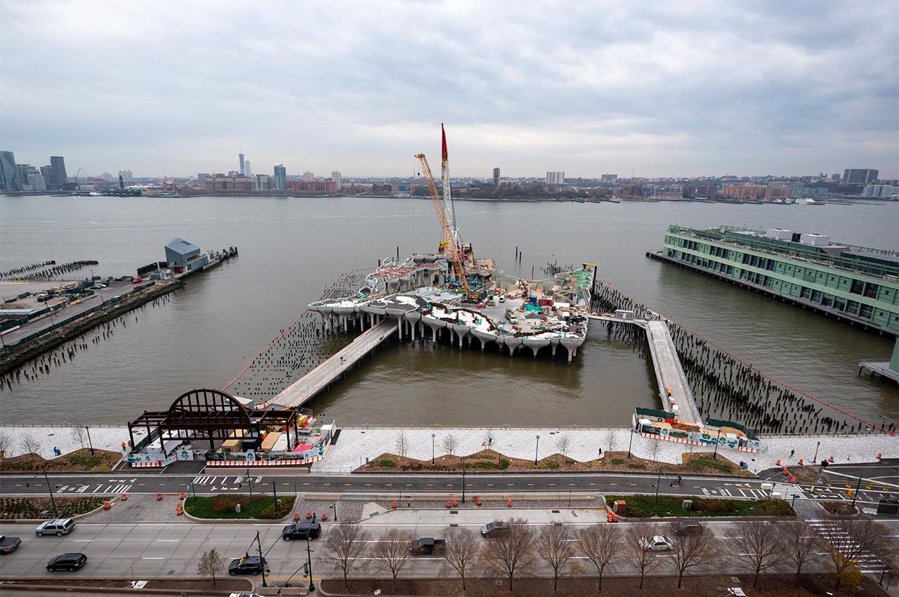
Little Island is an artificial island that is being built on the Hudson River, west of Manhattan, to provide a unique park experience for the New York public. It will be owned and maintained by the Hudson River Park Trust, a public agency, and operated by Little Island, a special-made organization specifically for the project.
Over the years, Hudson River Park Trust has successfully renovated old piers into public parks, recreational facilities or office and retail complexes. Little Island, a completely new structure on the river, will revitalize this section of Hudson River Park with almost three acres of new public park space featuring lush greenery and a diverse array of world-class arts, educational and community programming.
Under the overall design management by the prime consultant Mathews Nielsen Landscape Architect and in collaboration with the U.K.-based designer Heatherwick Studio, Arup was selected to realize the project vision for most engineering and consulting disciplines. Standard Architects is the executive architect.
Fort Miller Company (FMC) is the precast concrete manufacturer, Tymetal, a sister company of FMC is the steel fabricator, and Access Anvil/Scott System, another sister company of FMC, is the foam formwork fabricator and smooth formliner manufacturer.
Design Features & Challenges
The signature design of Little Island, featuring irregular, unique and complex undevelopable curved surfaces with few repetitions, sets it apart from other pier structures, but also imposes the most significant challenge for design, documentation, fabrication and erection. The geometry was not possible or practical to convey via conventional 2D documentation, so the team adopted an open approach to 3D modeling where we quickly realized that the only way to ensure geometry of construction would align on site would be a common design and construction model with the use of direct-to-manufacturing digital fabrication techniques for all the complex geometry elements.
Design
Construction on the Hudson causes challenges because of the marine environment which typically push designs towards prefabrication to remove the need for falsework. Pier construction generally consists of piles placed in the riverbed, topped with precast pile caps and planks, and tied together with cast-in-place concrete slab. These constraints make precast the right choice for this project, and the architect desired to use structural precast elements that would be exposed with architectural quality finishes. The precast technology would need to push past current convention to meet this vision. Also, a unique structural system has been proposed which is structurally effective, constructible and, at the same time, visually intriguing.


Pots
The deck structure consists of a unique module called ‘Pots’, tulip-shaped assembly of precast concrete elements. Typically, a pot is 4.5m tall and approximately 37m2 on plan area. A pot is supported by a 900mm diameter cylinder pile.
Each pot is composed of four to six ‘petals’, with thickened side struts and bottom edge beams, that sit on a central ‘column head’. The column head seamlessly transitions from the pot’s bulbous curved shape to the cylindrical pile geometry. The center of the column head acts as a vertical support for planks and ‘star beams’ above, which span radially from the center to the pot corners. Petal interiors typically transition from sloped to vertical moving away from the column head. Stainless steel embedded plates and welded external plates connect the petals to each other and the column head.
Pot Geometry Generation
The outside surface geometry of the pot is generated by the architect through a parametric script. Base rules of geometry are defined through discussions between architect and engineer to balance complexity with architectural vision. For example, the petal outer surface generally has a one-way curved surface except for edges where it rolls up to make the petal join smooth to the horizontal rebars can be straight with splicing edge bars that are booked and anchored in the cages of the strut bars. Internal surfaces are generated by Arup using another set of parametric algorithms added to the architect’s scripts to meet the required structural criteria and are geometrically simple to facilitate the conventional formwork fabrication for the interior surfaces. The joint between the column head and the petals is also defined making sure the connection using steel plates is feasible and the drainage of incidental water inside the pot is considered.
Rationalization
Although the overall layout and the plan shape of pots follow a specific pentagon called the Cairo-Pentagon, fitting them into an overall square plan with relatively straight edges and providing varying elevations access the top surface resulted in many different pot shapes. 39 different pot types resulted in 39 column head forms and 192 unique curved petal forms used to generate 132 pots and 656 petals. The curved exterior faces at the bottom portion of the pot are typical within pot types and the elevation variation required to meet the topography of the pier are achieved through pouring varying height ‘extension walls’. So, while each pot and each petal are unique, repetition of formwork was possible to a great extent. A few very special and complex pot types, particularly in areas over the southern access way and near the amphitheater, are only used once.
Structural Analysis Model Generation
On top of the scripts that generated pot geometries, another set of algorithms is added to generate a highly detailed analysis model in GSA, needed to design the rebar for all precast elements as well as connection plates and embeds. All design elements are explicitly modeled, and custom final member design post-processing tools were created to calculate the required rebars, steel plate sizes, and the number of studs, using model force outputs directly and quickly to generate the results.
Stainless Steel Connections & Light-Guage Sheet Metal Formwork Geometry Generation
Pot precast elements feature seven distinct connection types with multiple instances of each type based on upon petal and plank geometry. This resulted in an average of 35 pieces that may have unique set-out, unique geometry, and unique plate size and weld prep definitions, dependent upon overall pot geometry and loading. Over 15,000 plates are defined and set out parametrically. The light-gauge sheet metal formwork features 12 distinct elements to form the star beam elements. Slab geometry, which drives plank and steam beam geometry, is essentially unique across all pots resulting in over 7,700 elements in total that are defined and set out parametrically. The light-gauge includes bolt hole locations and cut-outs to avoid conflict with the steel connections.
Rebar Detailing Model Generation
Also generated in 3D using parametric scripts are the rebar models for petals and column heads. A completely detailed model includes all information needed for cutting and bending, including the clear cover, development and splice length, bending radius, etc. This was the major enabler for the realization of the complex precast elements.
Deliverables in 3D
All surfaces of precast elements, exact shape and dimensions of stainless-steel components, bent shape of light gauge stay-in-place formwork steel, and rebars in the complex petals and column heads are completely generated by the scripts with little manual adjustment. The resulting Rhino models, both the ‘as-in-place’ format in which all components are in their final location in 3D, and the ‘arrayed’ format in which all components are laid out on a 2D surface, are provided to the precast and steel fabrication contractors with full geometry for use in shop drawing production and final fabrication.
Coordination in 3D Environment
All design team members worked in 3D using either Rhino or other BIM software, and coordinated trades in 3D as well. A Navisworks model was created by importing each team member’s 3D components for coordination, clash detection, and for contractor’s information and reference.
Fabrication


Digital Fabrication
The fabrication team implemented new production processes to accommodate the 3D delivery of the construction documents in order to produce complex geometric shapes. In an environment where tape measures, people, wood and steel are the norm, the utilization of CAD/CAM technology, automatic equipment, and scriptwriting was a very novel concept that had to be implemented in order to fabricate the unique shapes within tolerance, work with a budget and meet the timeline of the project.
Fabrication Challenges
The doubly curved surfaces of the unique shapes presented the most significant challenge on the project. For the formwork, traditional mediums like wood and steel do not bend in doubly curved directions, urethane formliner lead times exceeded 48 months, carpentry requirement far exceeded current capacity and the formwork construction could not be quality controlled. Through the implementation of CAD/CAM subtractive manufacturing techniques in the production sequence, fabrication methodologies were created to build the formwork. The process included reverse engineering of the models and scripts generated during the design process for digital input of the geometry within CAD software to create the negative shape. Once created, the parts underwent a digital design process.

Model to as Built
The employment of digital fabrication for formwork production of complex architectural shapes allowed us to bridge the gap between architectural concepts and the built environment. To build the formwork for curved concrete elements, CAD/CAM subtractive manufacturing techniques, utilization of foam and polyurethane as new production mediums, and the employment of automatic equipment in a production sequence were the only means for fabrication. Large foam billets were cut on a CNC wire cutter into profiles to maximize the yield of material and to fit within the parameters of the CNC five-axis milling machine. Once cut, some assembly and prep work to the foam was required prior to placement on the CNC router.

Programming Methods
The engineering process included utilizing CAM software programming to direct and control the CNC cutting sequence and part verification software to ensure part fabrication feasibility prior to reaching the CNC machine. Prior to the part making it on to the machine, the fabrication team built a program that verified the toolpath developed by the engineer. The program that verified the toolpath developed by the engineer. The program provided data about the tool path and verified planned production run times for the team to utilize when planning a production schedule. In addition to building a production schedule, the program provided other information to the team allowing them to run parts through the night without supervision.

New Surface Treatment
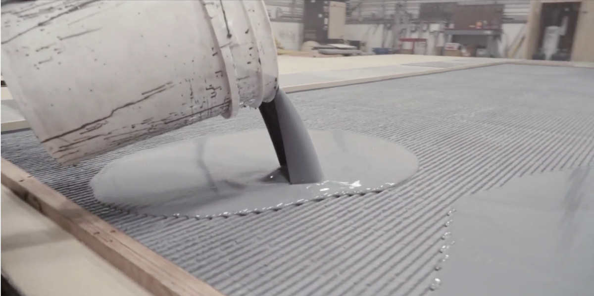
After the parts were milled and assembled, the surface aesthetic was applied. Traditional products such as architectural grade plywood or formliners are utilized to achieve the concrete finished on various construction projects. Due to the nature of the shapes and long lead times, a new method had to be implemented on a large scale that allowed the team to turn form over quickly, achieve a surface aesthetic required by the design team, and be used repeatedly for design economy. A high-pressure polyurethane product was applied to the form that met all the design criteria.
Automation of Shop Drawing Generation
The development of the form was the first challenge to overcome for the fabrication team, and the challenges continued to pressure traditional construction methods. Parametric programming software allowed the team to address other issues associated with the construction of the concrete shapes. The custom programs and scripts generated by parametric programs automated the process of creating 2D cross-sections and views from the 3D models of each pot to be used in the development of precast concrete shop drawings. Tables were developed for each rebar used in the production process from the 3D scripts that were generated from the design team’s scripts. The net effect of the scripts to produce shop drawings significantly reduced the amount of engineering time to develop 2D drawings manually for production. Data from the scripts had to be translated in an understandable way for manufacturing purposes. The use of custom programs converted the massive amounts of data into readable .txt and .csv files for manufacturing.
Digital Information Transfer
Manual methods of digital information transfer were not feasible. Equipment acquired had to speak the same language relative to the 3D models. The fabrications relied heavily on the tolerances of the CNC equipment to mill the forms, automatically bend the rebar and laser-cut the various embed places connecting petal to petal within a pot and unique steel geometry for stay-in-place formwork to hold the pots together. The sharing of information and connectivity between three different companies allowed the fabrication team to trust and verify each part was built to tolerance, would fit in its location and be set as needed, a unique communication experience.
Quality Control Using Digital Tools
The quality control procedures also relied on digital processes. Since the architectural shapes were undulating and not orthogonal, we digitally scanned the as-built part, downloaded the scan in to CAD software and overlaid the scan on the 3D model to verify the results of the part compared to the 3D model. The process provided a sense of tolerance control and further verification of the process.
Construction
All concrete and steel components fabricated at Fort Miller Company and Access Anvil were transported by lorry to the one-hour drive to the assembly site at Port of Coeymans on the Hudson river edge. A total of eight assembly stations were set up by the marine contractor to meet the tight schedule. Completely assembled pots were placed into the hopper barge that could store a maximum of four pots. A total of four barges operated in turns for delivery of the assembled pots to the project site.
Site Erection
Pots arrived at the site in the barge and were dragged by tugboat to be erected by a floating crane on to piles. A well-planned erection procedure meant on pot was erected in a few hours.
Topping Slab
Finally, the cast-in-place topped slab was pouring to tie all the pots and the flat pier together and create a monolithic, highly indeterminate moment-frame pier structure.
Little Island is a ground-breaking departure from conventional pier construction and utilizes the lastest advances in digital design and fabrication technology to successfully deliver a structure that is both functional and playfully sculptural at the same time. The major challenge of generating, engineering, communicating and fabricating the complex geometry was overcome with intensive use of parametric scripts, automation and digital data communication in the design phase, and the use of milled foam formwork and bending rebar using a detailed 3D model in the fabrication phase. The collaboration between all parties to deliver this project was critical in achieving a successful outcome for future generation to enjoy. When complete, Little Island will be a new icon of the west side, and a visible reminder of what can be achieved when the conventional scoping boundaries of contractors and designers are blurred, and project participants come ready to collaborate.
Rim Snaps Inlay System: What is it & How Does it Work?
As a leading manufacturer of products for architectural concrete, Scott System has laid the groundwork for concrete textures and architectural solutions for decades. The innovative and time-saving Rim Snaps™ inlay system offered by Scott System creates the versatility needed when casting in-place concrete for clean and functional vertical bridge components like bridge parapets, abutments, and…
Benefits of Extended-Use Urethane & ABS Plastic Concrete Formliners
Different types of extended-use formliners can provide distinct looks on concrete for a wide range of projects. They can also bring an aesthetically pleasing appeal to a variety of finished products. Before beginning your company’s next project, be sure to fully understand the benefits of extended-use concrete formliners offered by Scott System. Each project material…
What Are Brick Snaps®& How Do They Work?
Brick Snap® inlay systems are innovative concrete construction solutions that can speed up and simplify projects, as well as reduce overall costs, while still producing top-quality creative architectural designs with the look and feel of traditional brick. The revolutionary façade system plays an integral role in casting brick into precast or tilt-up concrete, which can…